Hello everyone,
Welcome to the first tutorial post in the 1BitSquared forum. 
People ask me on a regular basis what reflow oven I am using. I use two fully upgraded/modified T962a reflow ovens. You can get them from eBay for around $300, give or take. I heard some people had some success using toaster ovens with modifications for reflow but I personally do not trust that solution enough from the safety standpoint. Also from what I can tell the toaster oven conversions end up being more complicated than the T962A oven conversion. Still as always, use what works for you. I am just sharing what I am familiar with, so take my criticism with a grain of salt. 
The most important note is to make sure you get a T962a and not the less powerful T962, you will need the power to be able to reliably follow a reasonable reflow temperature curve.
That said the T962a is close to useless when you get it and you need to make a few modifications to it. If you don’t make those modifications you will create a safety and health hazard. Also you might burn up your PCBs or evaporate the flux from your solder paste before it reflows creating cold solder joints.
The closest thing that I could find, that could be an out of the box working replacement, is about 10 times more expensive than the T962a including the modifications.
These are the supplies you will need:
- Screw drivers (a few sizes of Philips and a tiny flat screw driver)
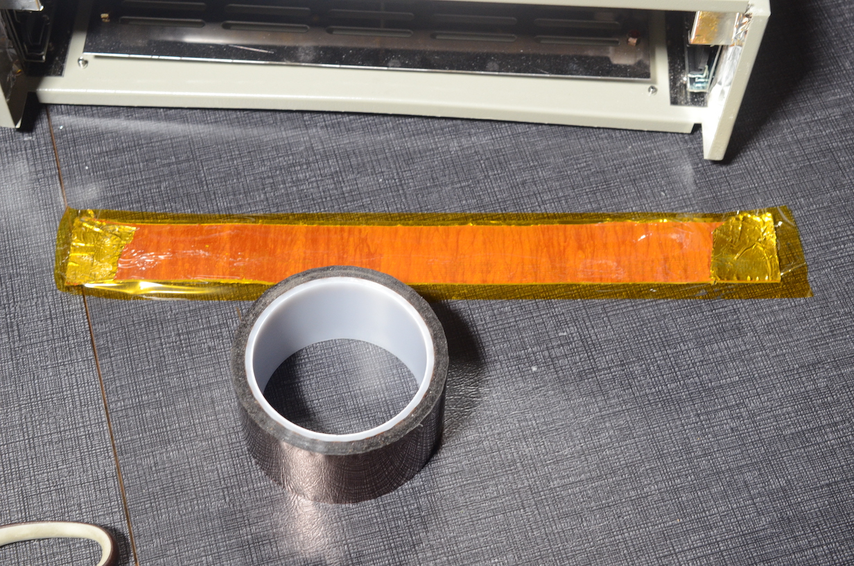
- medium width Kapton tape (1" wide or equivalent, you can use other widths but this one seems most appropriate for the project)
- Multimeter
- Small file or other scraping device
- A serial to USB adapter. (and FTDI cable is an adequate choice, you can also use Glasgow or Tigard)
- Soldering iron
- A little bit of wire
- Thermocouple interface board with parts
- A small replacement “silent” 40mm fan (optional)
And these are the following steps you need to perform to modify your oven.
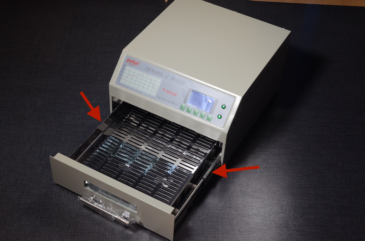
Open the oven
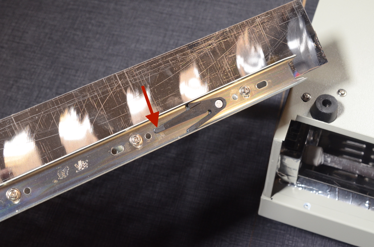
You have to remove the drawer first. It hides some screws for the top lid. To remove the drawer, you need to pull it out and lift the black latches inside the rails that keep the drawer captive.
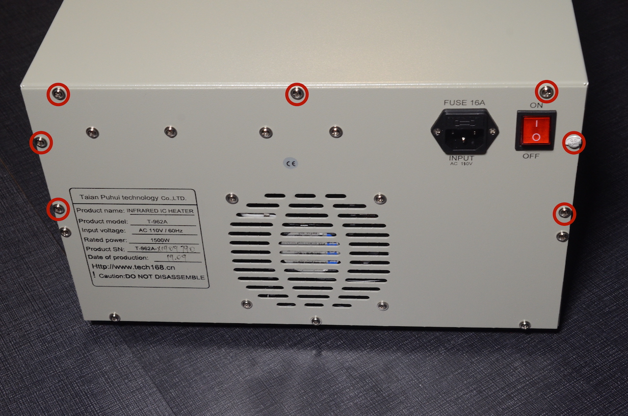
Then you can remove the screws under the top lip of the oven drawer opening.
The oven is screwed together on the back. You will have to remove the screws in the back that keep the top lid on.
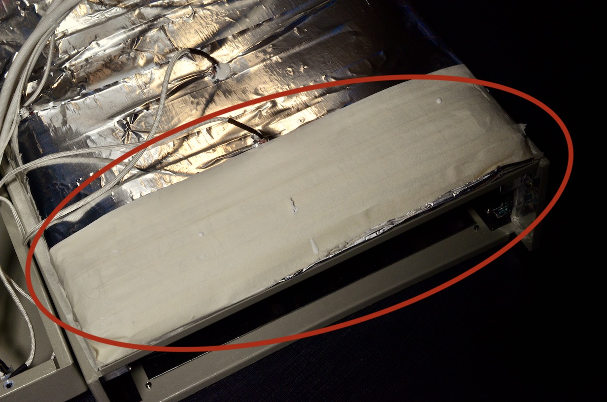
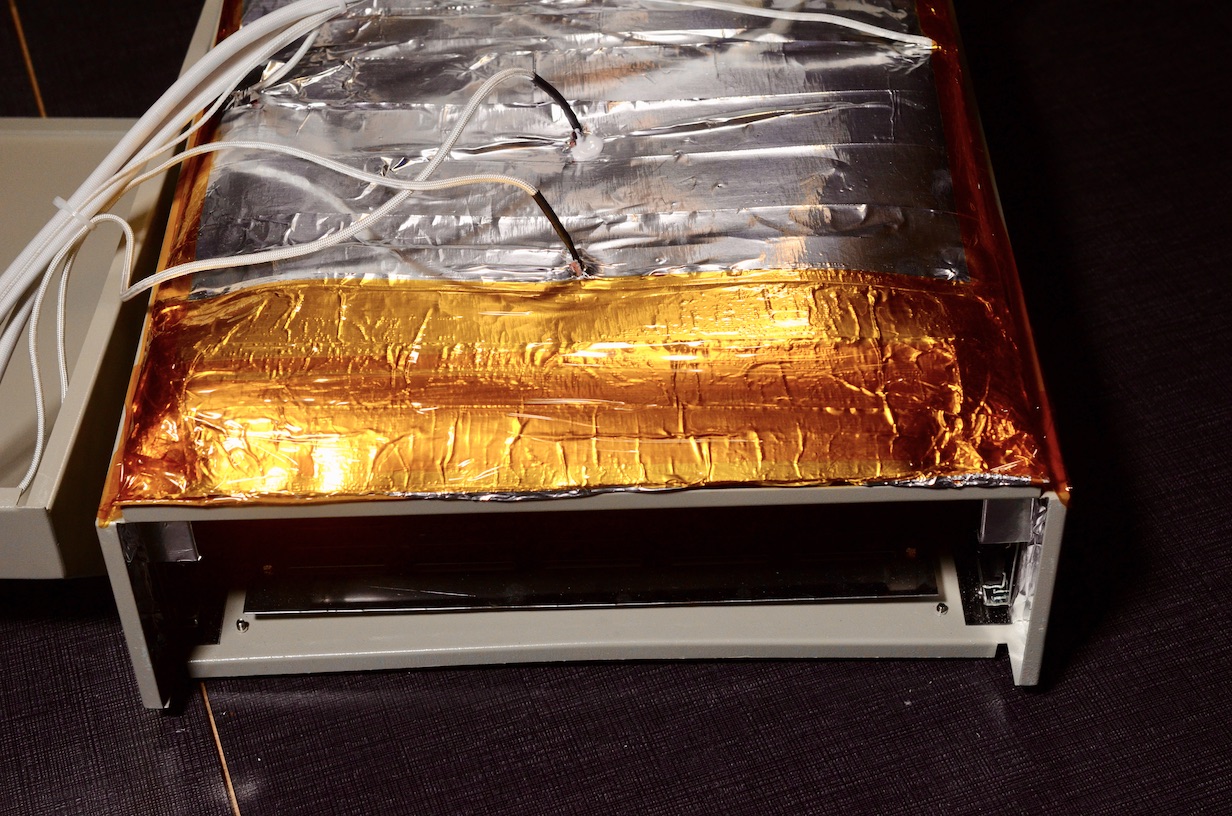
Remove and replace masking tape
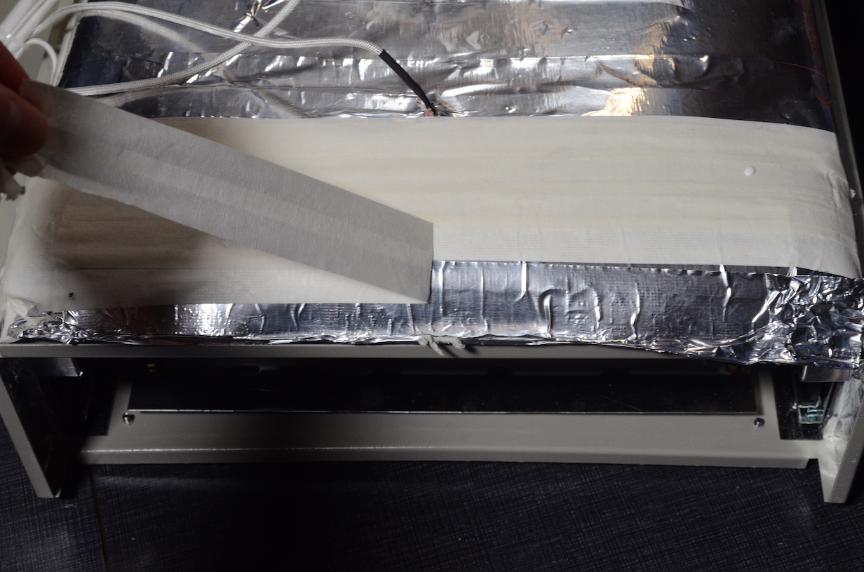
You might be lucky, but for many years the ovens have been shipping with a layer of masking tape keeping parts of the insulation together. You MUST NOT run the oven with the masking tape in place. Make sure to replace it with kapton tape before you run the oven for the first time. The masking tape will heat up and release very nasty fumes that are probably not good for you. I have recently heard the first person receiving an oven that did not have the masking tape inside. So maybe they have finally stopped using it. Still you have to open the oven and check for yourself.
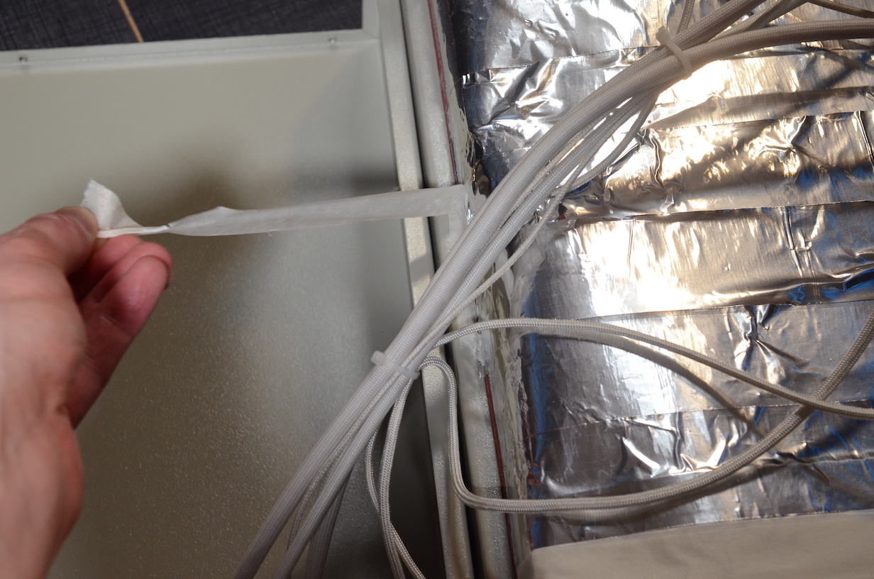
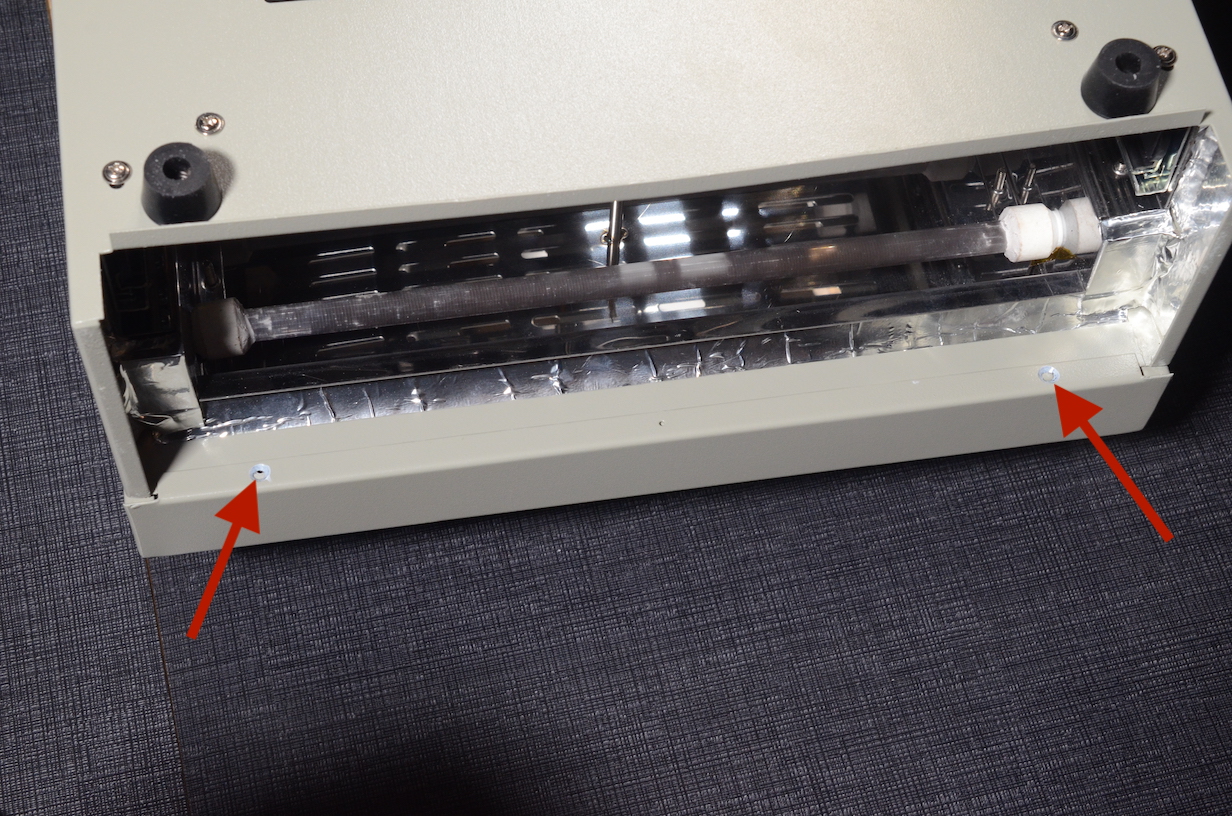
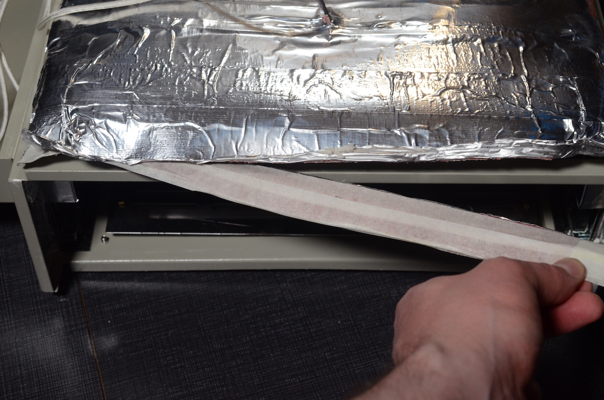
Do not forget to remove the “ruler” above the front oven tray lip. It is a sneaky hidden place where some more masking tape is hiding. (see following image)
Now after removing the masking tape you can replace it all with Kapon tape.
Earth the case
All the ovens that I have received so far were not properly earthed. Even though there usually is a wire going from the earth pin of the mains connector to the case, it does not make contact with the metal under the powder coating.
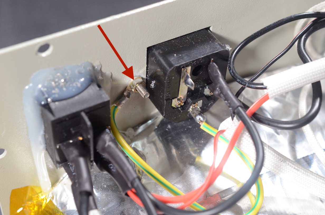
Use your multimeter in continuity mode to check if the earth pin has continuity all the way to your oven drawer rails. You will probably have to unscrew some more screws and rough up the powder coating to make a connection. It usually goes from the earth pin to the back plate and from the back plate to the bottom shell of the oven. In most cases it is enough to rough up two screw contact surfaces to make a connection.

You might be asking why this is important. If there is a short from the live mains to the case of your oven you don’t want to get a shock. If the case is not connected to earth, your earth leakage circuit breaker of your home wiring will not get triggered and you will get a shock. If you make the connection then the leakage of the current from your hot wire to the case will be detected and you will pop the fuse not your heart. If you are curious about GFCI/RCD there is a really good video from Technology Connections about the topic.
Re-flash the controller
There is a really good replacement firmware for the controller board found in your oven. You don’t have to buy a new controller board which is nice! You can download the replacement firmware hex file from the releases section on the Unifiedengineering GitHub page.
I highly recommend that you disconnect the heater relay control wire before you continue. You can connect it again after you are done updating the firmware.
You can follow the instructions on how to flash the firmware on their wiki.
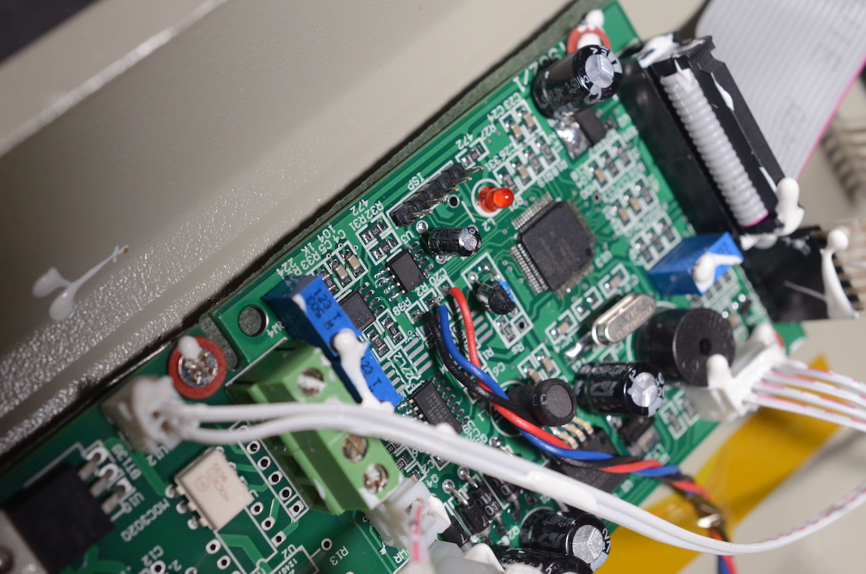
The connections on the controller board are not fully clear in the wiki. So here is a pin-out legend.
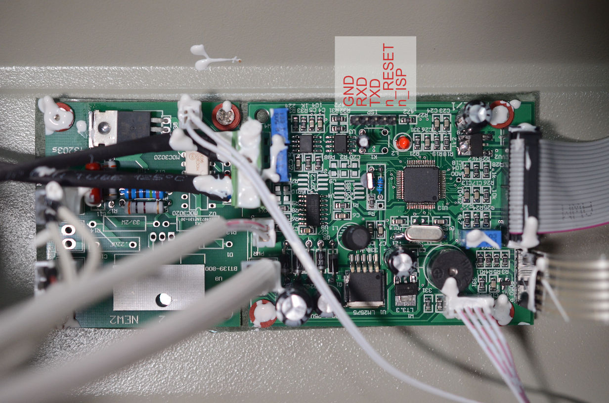
RXD and TXD is from the controller perspective as convention dictates. So you will be connecting your USB to serial adapter cable TX signal to the board RX signal and vice versa. But as always it is easiest to just hook it up, check if it works or not and then try swapping the cables if things don’t work. It is much faster than wrapping your head around what is what. 
I used a EZ-Hook clip to connect ground to the n_ISP pin and then used a second GND wire to pulse the n_RESET pin.
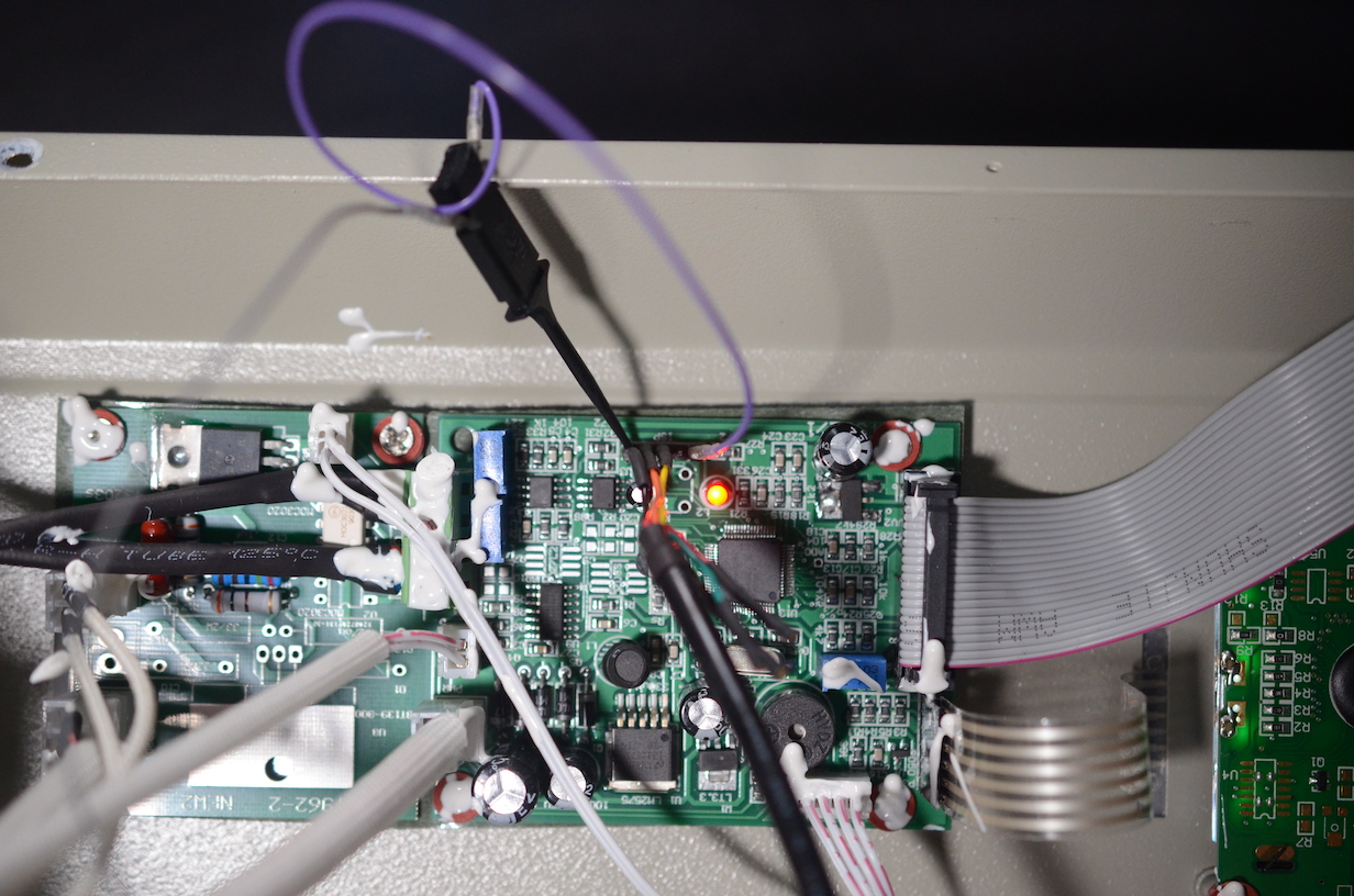
A much nicer solution is to use a programmer that has support for the n_ISP and n_RESET pins. Possible candidates are Glasgow or Tigard.
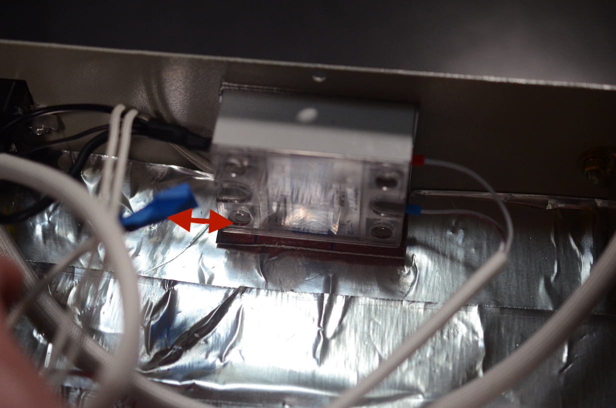
Build the Thermocouple interface board
The controller that the ovens ship with use generic opamps (Operational Amplifiers) to measure the oven temperature with the thermocouples (temperature probes). Due to manufacturing differences those probes and the circuit needs to be adjusted. This is why they have two trimpots (trim potentiometers) on the board.
The problem with that solution is that it is very inaccurate. If you trim the pots to have accurate room temperature reading, the measurement will be off when the oven heats up to 200deg C. Another problem is that you need so called cold junction compensation. The Unifiedengineering documentation shows a way of adding a separate temperature sensor for cold junction compensation. I tried that solution, it does help, but the oven is still reading very inaccurate values.
This is why I really recommend that you invest in the Thermocouple interface board and mount it in the oven. I know the chips are expensive but they are worth it. You can often find these chips for a reasonable price on LCSC. (A few people asked me if I can sell them the boards. I am working on this and as soon as they become available in the 1BitSquared store I will update this post.)
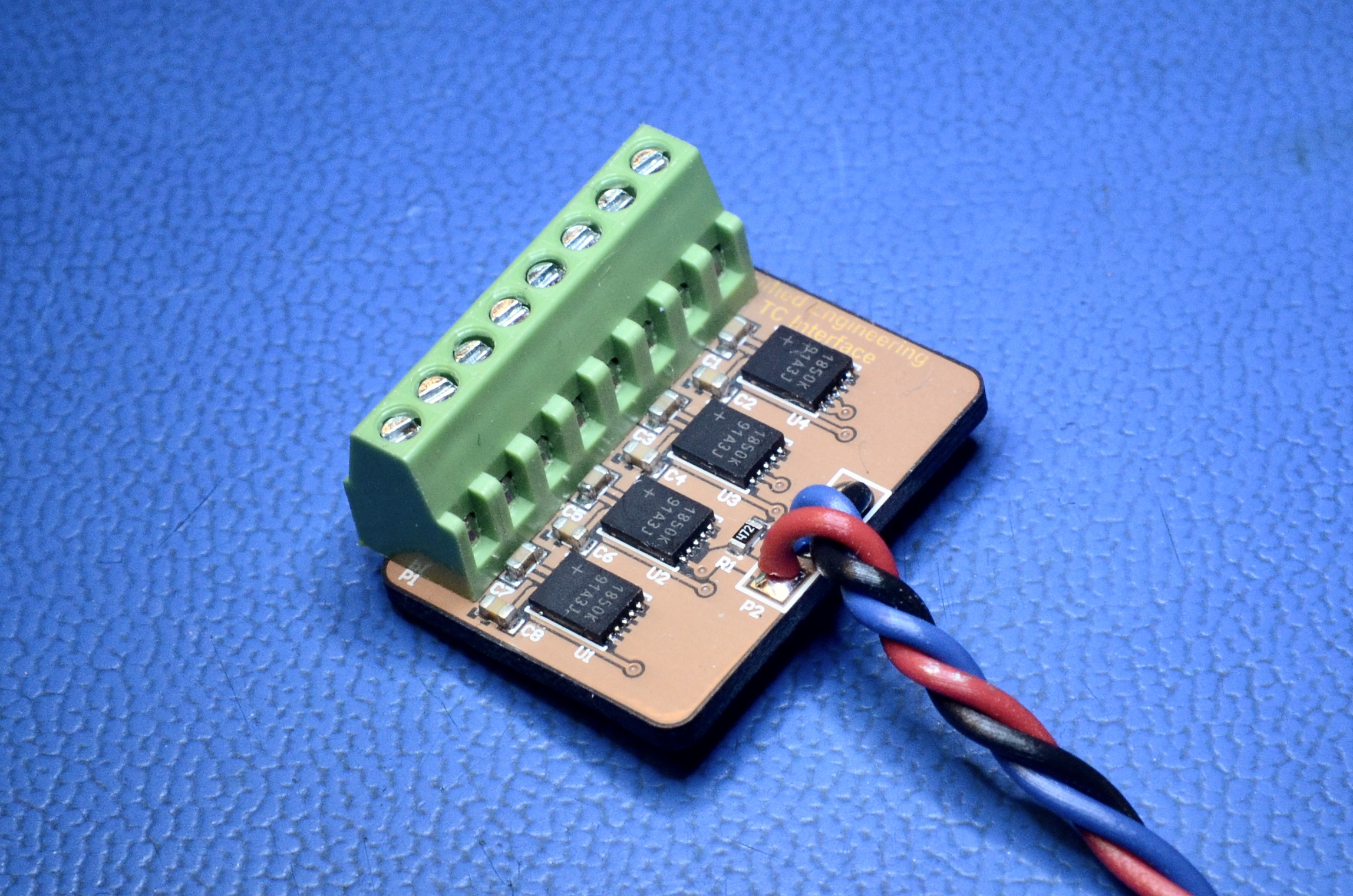
If you are not planning to use the two additional aux thermocouple channels. You can save some money and only populate the U3 and U4 footprints. (Yes the last two, it is bit counter intuitive and the two channels that are used for oven temperature control are the last two channels) But if you want to track temperature on your PCB or do calibration and tuning of your reflow profiles, it is worth having the additional probe inputs.
The oven controller board facing pinout of the thermocouple interface board is as follows:
VCC-
Signal(1Wire interface) GND
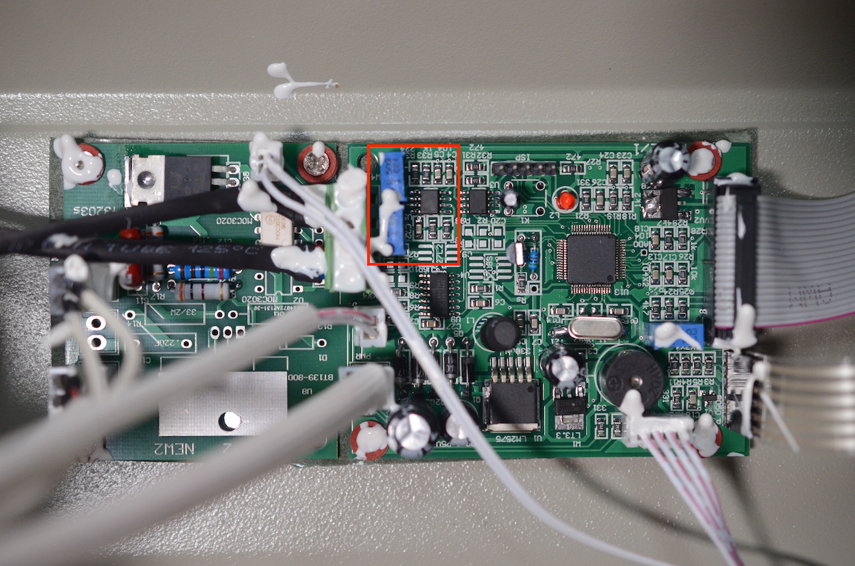
You have to solder them to the following footprint pads on the controller board:
C20R2C9
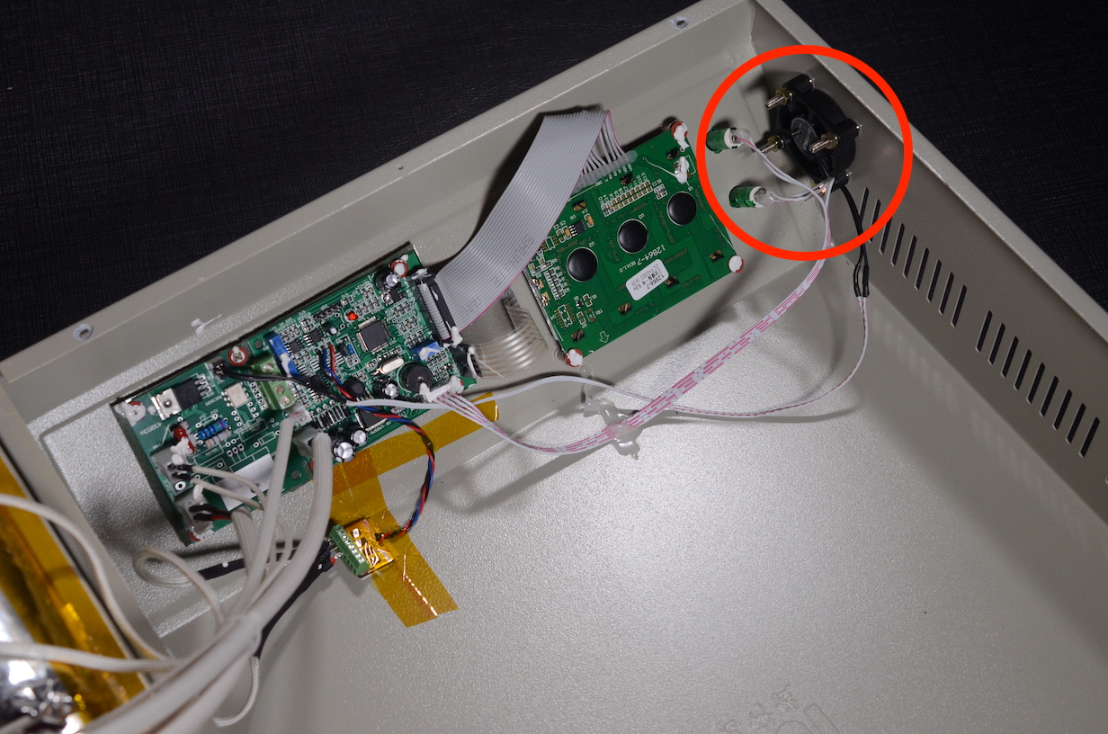
Now you can disconnect the thermocouples from the controller board and connect them to the new thermocouple interface board.

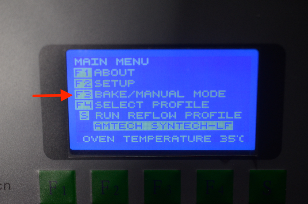
Unfortunately the colors of the thermocouples and their sleeves are not well standardized, so you might need to experiment a bit and swap things around until they work. You will probably have to switch on the oven and start the manual heating program to figure things out.
Here are some troubleshooting tips:
- If the oven is heating but the oven indicates that the temperature is falling, you have to swap the leads of the thermocouple.
- If the oven reads an unbelievably huge temperature value, check your thermocouple connection, it might have slipped out of the terminal block and is not connected properly.
Replace the electronics cooling fan
This step is optional. The oven does ship with a fan that works but I found it to be very shabby and sometimes even rusty. Also it is very loud for no reason. Small “silent” PC fans work well as a replacement. Since you have the oven open already it is a good opportunity to replace the fan now.
A typical PC fan will have holes that are likely too small for the screws used in the oven, so you might need to drill them out. The cable on the PC fan will also probably be too short so you will have to extend it. I used the wire from the included fan to extend the wires of the replacement, and tidied it up with some heat shrink tubing.
Additional mods
The pins used for firmware update can be used as a computer interface. You can add a serial socket, A USB to serial adapter with a socket or a serial to wireless adapter to your oven. There is a VisualBasic PC software that allows you to track reflow curves and calibrate them. I have not played with it as my oven works well enough as is. But it could be an interesting project.
Another possible mod is adding sockets for the auxiliary thermocouples to the oven. This would be interesting in combination with the PC software interface. I have used them once to validate my curves and check what the offset between ambient to PCB body temperature is.
Usage notes
- Pre-heat the oven to 40C before use.
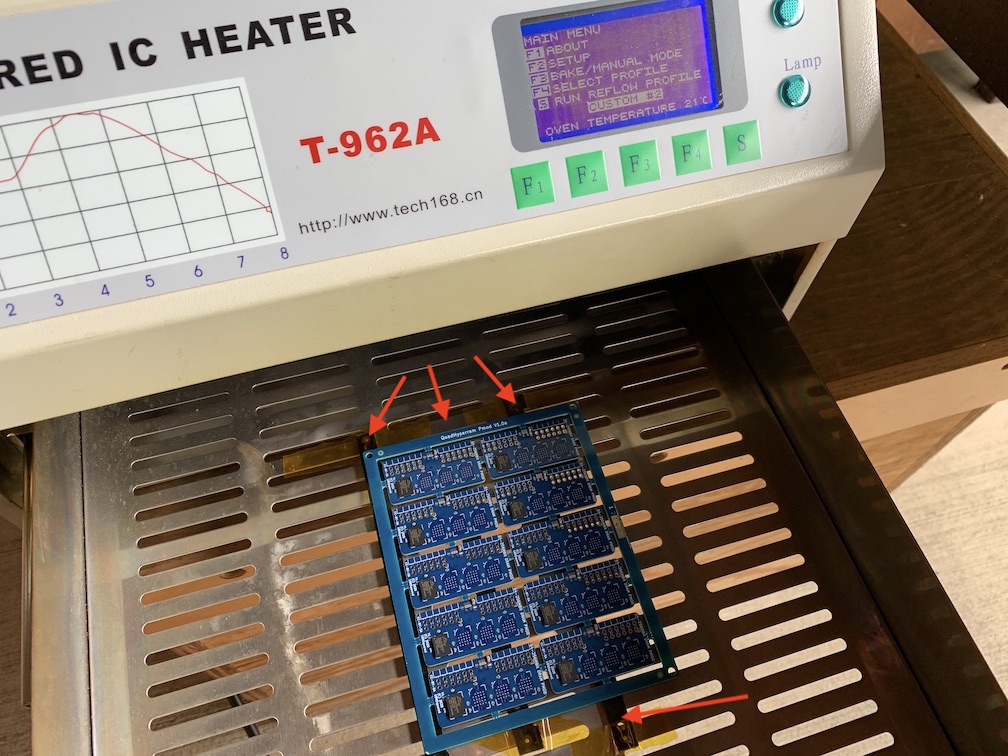
- Put down some scrap PCB material under the board you are reflowing so that it is not sitting directly on the metal tray. If you don’t do that the tray will act as a heat sink and suck out valuable heat from your PCB and cause problems.
- Use only the center 1/3 to at most 1/2 of the oven tray. The outer area of the reflow tray will not have the same temperature as the center and you will have reflow consistency issues around the edges of your PCB’s. This is a good reason to design your boards as small as you can so that you can squeeze a bunch of them into the center of the oven. ;D I am being told that this evenness issue is what the professional batch ovens are better at.
Final thoughts
If you have all the supplies, this modification should take no longer than one afternoon and it is really worth it!
I hope this helps. Let me know if you have questions or suggestions. I hope to continue improving this guide as more people in the community build T962A based batch reflow ovens.
Huge thanks to Brian Swetland who allowed me to convert his oven, and make the photos. I did not document the conversion process on my ovens, so without his help this tutorial would not be possible.
Cheers,
Esden
P.S. This post is based on a blog post I wrote a while ago. I am posting it here with updates, photos and improvements, to hopefully seed a conversations about electronics manufacturing tools here in the forum.
P.P.S. If you converted an oven yourself make sure to share your story/guide too.