I will probably convert that to use the HDMI Pmod.
I am looking at porting the NES games console implementation that @daveshah had working on an Upduino UP5K device a couple of years ago, to the icebreaker, and to see if I can make that work with HDMI.
Welcome to the forum. That is awesome thank you for sharing, and keep us up to date on your progress!
I am glad to see that people are resurrecting some of the old systems on the iCEBreaker. I got some SNES controller connectors not so long ago. I need to find time to make some PMODs for them. It would be great to connect them to the iCEBreaker and play some old games.
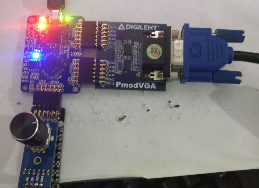
I have struggled in the last day or so to make @daveshah’s Upduino version work. I was getting nothing on the VGA for a while and thought there was a problem there. But after some experiments, I found it was OK - it was just that nothing was being written to the screen.
I modified the game selection to simplify it with just one game in flash memory and one button to reload it. That freed Pmod 2 to use with a 8 led strip for diagnostics. I slowed down the CPU and looked at the data being fetched and it did not look right, so I suspected it was not copying the ROM from flash memory to SPRAM correctly.
I suspected it may be because the flash memory on the icebreaker goes to sleep and needs waking, but does not on the Upduino. So I added a -s flag to icepack, which stops the flash memory going to sleep, and that fixed the problem.
I have not attempted to use a controller yet.
The timing analysis in nextpnr and icetime says that the design will only run at 8Mhz, but it appears to work at 12 Mhz. It was even worse in the Upduino version that uses arachne-pnr. The call to icetime in the makefile had been commented out, so I suspect it worked on the Upduino despite icetime’s pessimism.
Using nextpnr also results in a lot fewer LCs being used, so the audio might now fit.
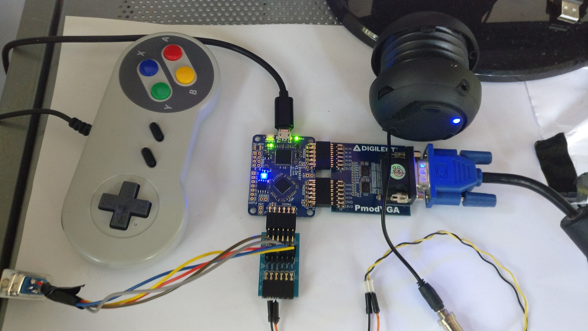
The code is probably working now. The issue I have is probably just the clone controller. It would probably work fine with a genuine Nintendo controller (or a better clone).
Yes, a PMOD with an audio socket and a 7-pin controller socket would be good. The clone controllers usually have 9-pin DB9 connectors, so would need a different PMOD.
Maybe the Pmod should just have pin headers/sockets that you wire the connectors to? This way it is more flexible and you can wire the connectors into a project box?
That part is also a mystery to me, as I’m a total FPGA beginner :D. That code was copied by me from the original mist port and adopted to suit my needs. I was first using some buttons wired to the pins with a shift register implemented on the FPGA side and that worked. Then I tried removing the shift register code and directly connecting the controller I have but the input was pretty messed up: pressing up was doing a down and so on.
I’m also using a chinese cloned joystick with DB9 connector. I tried the controller with an arduino sample code for reading the inputs but that worked as expexted. Then I hooked my fx2la login analyzer to the pins of the controller and the captured data was just as the original NES. I have no idea why it doesn’t work. Maybe @daveshah can share some light on what controller he was using and did it work when he ported the NES to the upduino.
Yes I’m running it on the Olimex iCE40hx8k-evb board which has 512Kbytes of external ram.
I also have a BlackIce2 board but my current setup with the olimex one is easier to wire up as I also have the ice40-IO expansion from olimex with the VGA connector.
I’m also waiting to get my icebreaker board so I can also try the DVI PMOD with the NES.
Right now I’m pretty much passing timing on the hx8k device:
Info: Max frequency for clock ‘clock’: 23.14 MHz
SDRAM would be kind of difficult from a timing point of view and amount of logic used but I’m also keen on trying that path. Maybe I’ll have to buy the BlackIceMX to try that.
Looking forward to seeing your progress on this.
One thing @daveshah suggests in his readme is trying to ‘stream’ the games from SQI flash but that
would be a no go zone for me as I’m not so experienced.
He said, he used an original Nintendo controller with the 7-bit connector. He confirmed it worked at 3.3v, which I was not sure about.
A problem with that board is it has no flash memory, so loading the game will be harder. I would either have to put it in in the STM32 flash memory and transfer it to the ice40 with SPI, or read it from an SD card, which is not that easy.
I will try this sometime. I had a discussion with @daveshah and @esden about it yesterday, and Dave pointed me at some code. I am still a relative beginner at this, but have been doing it for about a year and a half since I got my Blackice2 board, and am beginning to get the hang of it.
I have SDRAM working on that board but only with SpinalHDL and not very fast, but fast enough for this I think. I believe Dan Gisselquist (Zipcpu) also has a working SDRAM controller for it. That board has flash memory, but not a lot of it.
Yeah I think that is correct. We just need the additional data pin for another controller. We should probably start a new thread and write down requirements and ideas regarding that Pmod. There are also people on twitter that have some ideas we could incorporate.
Ok I started the new topic for the Pmod… let’s see what we can come up with
Hi…A monitor always displays a picture line-by-line, from top-to-bottom. Each line is drawn from left-to-right.
That’s hard-coded, you cannot change that.But you specify when the drawing starts by sending short pulses on HS and VS at fixed intervals. HS makes a new line to start drawing; while VS tells that the bottom has been reached