In my understanding, PMOD Digital Video Interface only requires two 12-pin Pmod, which Basys3 has.
If Basys3 supports PMOD Digital Video Interface, where can I find some reference projects about this Pmod DVI? In other words, how can I use this Pmod DVI on Basys3? If not,why? Are there other restrictions(in hardware or software)?
Wish your reply, thanks a lot.
As you can imagine we are not spending time developing examples for third party development boards, but rather for our own. But you might be able to port the iCEBreaker examples to your board without too much trouble.
Thanks for your reply.
I wonder the differences between iCEBreaker and iCEBreaker-Bitsy FPGA dev boards.
If I want to port the example projects you provide to my own board, does that mean I only need to modify pins assignment?
And, where can I find the price of Pmod DVI?
Hope your reply.
The answer is in the name. bpp stands for Bits Per Pixel. Meaning:
The 4bpp has 4 bits per pixel. One bit per each part of the pixel color: 1 bit Red, 1 bit Green, 1 bit Blue and 1 bit Saturation level. This is similar to CGA colors and requires one Pmod 8 physical data pins connection. The pixel data is sent on each rising edge of the pixel clock. Here is the schematic.
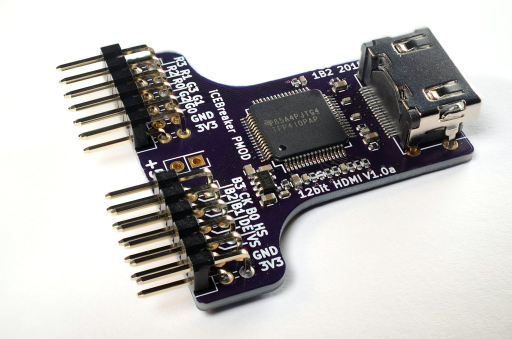
The 12bpp has 12 bits per pixel. 4bits per each part of the pixel color: 4 bit Red, 4 bit Green, 4 bit Blue. This requires two Pmod, 16 physical data pins connection. The pixel data is sent on each rising edge of the pixel clock. Here is the schematic.
The 24bpp DDR has 24 bits per pixel. 8bits per each part of the pixel color: 8 bit Red, 8 bit Green, 8 bit Blue. This requires two Pmod, 16 physical data pins connection. Half of the pixel data is sent on the rising edge and the other half is sent on the falling edge of the pixel clock. Thus the name DDR (Double Data Rate). Here is the schematic.
Due to how the encoder chip works and how it’s wiring is designed, each of these modes requires a separate wiring of the PCB. This is why there are three different Pmods available.
I recommend you spend some time reading the datasheet of the encoder chip itself. You will get the underlying understanding on how the encoder chip works. What you need to do to send your pixel data and so on.